Uml State Diagram Vs Flowchart
A state diagram, also known as astate machine diagram or statechart diagram, is an illustration of the states an object can attain as well as the transitions between those states in the Unified Modeling Language (UML). In this context, a state defines a stage in the evolution or behavior of an object, which is a specific entity in a program or the unit of code representing that entity.
A state diagram resembles aflowchart in nature; however, a flowchart shows the processes within a system that alters the state of an object rather than the actual state changes themselves. The first step to creating a statechart diagram is identifying the initial and final states of a system. Then, all of the possible existing states are placed in relation to the beginning and the end. Lastly, all of the events that trigger state changes are labeled as transition elements.
Symbols and components of state diagrams
The structure of a state diagram depends on the system being modeled, but typically includes the following components and notations:
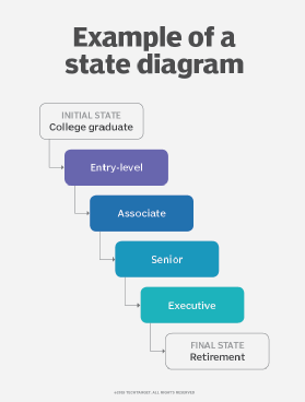
- Initial state- Usually marked by a solid black circle, this represents the initial state of a system or a class.
- Middle states- These are portrayed as boxes with rounded corners. There may be one or two horizontal lines through a box, dividing it into stacked sections. In that case, the upper section contains the name of the state, the middle section (if any) contains the state variables and the lower section contains the actions performed in that state. If there are no horizontal lines through a box, only the name of the state is written inside it.
- Transitions- External straight lines, each with an arrow at one end, connect various pairs of boxes. These lines define the transitions between states.
- Final state- The final state is portrayed as a large black dot with a circle around it.
In addition to these basic components, state structure diagrams can include the splitting of one state into multiple states, the conjoining of various states into one state, self-transitioning states, composite states and historical states.
Self-transitioning states occur when a certain activity or event does not alter the state. Historical states are denoted as circles with the letter H inside.
Uses of state diagrams
State diagrams can be useful in a variety of applications and in all forms of object-oriented programming (OOP). This type of UML diagram is helpful for:
- Listing the events responsible for altering system states.
- Modeling dynamic behavior and activity of a system.
- Understanding the response of a system to different types of stimuli.
- Representing finite state machines graphically.
- Visualizing the entire lifecycle of an object.
Example of a state-based system
A system that can be modeled with a state diagram could be an ATM. The initial state of the system is "ready" to be triggered into action by a customer. Middle states could include verifying the user, processing the request or malfunctioning. Events are determined by the user, such as checking bank balance, withdrawing cash or depositing a check. The final state is reached when the machine successfully executes and ends a session.
This was last updated in May 2019
Continue Reading About state diagram (state machine diagram or statechart diagram)
- Why Do We Need Architectural Diagrams?
- Altova provides XML transforms, charts, code generation
- Build your knowledge of UML diagrams
- 4 development tools that bridge the architect-developer gap
Dig Deeper on Application development and design
-

data flow diagram (DFD)

By: Tom Nolle
-

Build apps with these cloud architecture diagram examples

By: Kurt Marko
-
Diagrams.net vs. Lucidchart: A few things to consider

By: Kerry Doyle
-

A better Gitflow diagram with branches, merges and color

By: Cameron McKenzie
Source: https://searchapparchitecture.techtarget.com/definition/state-diagram-state-machine-diagram-or-statechart-diagram
Posted by: eirlsdaltonnoes.blogspot.com

Posting Komentar untuk "Uml State Diagram Vs Flowchart"